vacuum pipe identification

Moderators: theelanman, dapinky, Specky, clemo, Nige, Sy V, Dave Eds, DaveT, Elanlover, muley, Enright, algirdas, nitroman, GeoffSmith

vacuum pipe identification

Postby scotlan » Fri 08.05.2020, 10:04

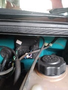
I have a severed Vacuum pipe hanging free. As can be seen in the photo it is shown running from front to back of the pic. it clips to the bulkhead and then goes across the bulkhead and then through it with a similar diameter pipe.
My questions are: What does it do? where does it start from at the manifold? is there a required union to attach it to and what diameter is it?

The answer to one or more of these questions would be appreciated
Image
User avatar
scotlan
Enthusiast
 
Posts: 139
Joined: Sat 01.01.2011, 10:51
Location: Perth, Scotland

Re: vacuum pipe identification

Postby lotustonybassplayer » Fri 08.05.2020, 11:55

it goes to the vacuum reservoir behind the wheel arch liner. it starts from the rocker cover right hand side at the rear just in from the corner you should see a little spout where it connects to. It usually has a right angle rubber connector, i've just replaced mine it comes from a mini distributor £1.75 on Ebay part no 12B2062
lotustonybassplayer
Fanatic
 
Posts: 349
Joined: Wed 09.05.2012, 21:40
Location: rainham kent

Re: vacuum pipe identification

Postby scotlan » Fri 08.05.2020, 14:34

lotustonybassplayer wrote:it goes to the vacuum reservoir behind the wheel arch liner. it starts from the rocker cover right hand side at the rear just in from the corner you should see a little spout where it connects to. It usually has a right angle rubber connector, i've just replaced mine it comes from a mini distributor £1.75 on Ebay part no 12B2062


Lotus base player, thanks for your input. I should have said, I have 2 severed pipes. One is that which you refer to, the other heads in the opposite direction, effectively from the passenger side to the driver's side along the bulkhead. It has a smaller diameter, it is this one I am needing help with.
User avatar
scotlan
Enthusiast
 
Posts: 139
Joined: Sat 01.01.2011, 10:51
Location: Perth, Scotland

Re: vacuum pipe identification

Postby GeoffSmith » Fri 08.05.2020, 16:07

Possibly the heater valve.
Calypso Red S2 #417

USB ElanScan interfaces - £60 incl. UK P&P & £65 incl. ROW P&P
User avatar
GeoffSmith
Kitty Fiddler
 
Posts: 15628
Joined: Fri 03.02.2006, 21:57
Location: S2#417 in Tytherington, Gloucestershire

Re: vacuum pipe identification

Postby scotlan » Fri 08.05.2020, 18:54

GeoffSmith wrote:Possibly the heater valve.


Image

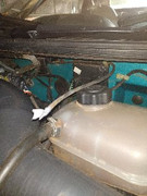
Geoff, thanks for your reply, I thought you'd hit the nail on the head so I went to check. There is one vacuum pipe attached to the valve which is in tact. My severed one meets up with that one on the bulkead and travels with it until they both go through the bulkhead one slightly above the other.

I attach a new picture it's the one sealed with tape.Thanks
User avatar
scotlan
Enthusiast
 
Posts: 139
Joined: Sat 01.01.2011, 10:51
Location: Perth, Scotland

Re: vacuum pipe identification

Postby johnj » Sat 09.05.2020, 21:10

I think that if you look almost directly down from where the end of the broken hose is, there is a Y shaped hose. If you follow the Y back towards the bulkhead there us a circular metal 'thing' (sorry not mechanic'). It has a nipple at the bottom. I think the pipe connects there.
johnj
Enthusiast
 
Posts: 178
Joined: Mon 04.01.2010, 23:56
Location: Cumbria

Re: vacuum pipe identification

Postby scotlan » Sun 10.05.2020, 10:46

johnj wrote:I think that if you look almost directly down from where the end of the broken hose is, there is a Y shaped hose. If you follow the Y back towards the bulkhead there us a circular metal 'thing' (sorry not mechanic'). It has a nipple at the bottom. I think the pipe connects there.


Thanks JohnJ. I have checked what you described, found the Y hose and followed it back to the bulkhead but I'm unable to identify the circular metal thing you mention.
I have a friend with an S2 who lives a couple of miles away... as soon as lockdown is over I will look at his to see if I can follow up on what you suggest.
User avatar
scotlan
Enthusiast
 
Posts: 139
Joined: Sat 01.01.2011, 10:51
Location: Perth, Scotland

Re: vacuum pipe identification

Postby johnj » Sun 10.05.2020, 13:55

See attached picture, bottom hand pointing to the Y hose. Top hand pointing to the metal piece with tube attached.

Hope this helps.
You do not have the required permissions to view the files attached to this post.
johnj
Enthusiast
 
Posts: 178
Joined: Mon 04.01.2010, 23:56
Location: Cumbria

Re: vacuum pipe identification

Postby scotlan » Sun 10.05.2020, 14:35

johnj wrote:See attached picture, bottom hand pointing to the Y hose. Top hand pointing to the metal piece with tube attached.

Hope this helps.


First, I must thank you for showing me by taking the picture. You must have gone to some trouble as both of your hands are in the picture!
However this pipe is in place and intact on my car. The pipe which I am trying to identify comes out of the bulkhead right next to "yours" and then across the bulkhead and I don't know where it should end up.
Thanks again
User avatar
scotlan
Enthusiast
 
Posts: 139
Joined: Sat 01.01.2011, 10:51
Location: Perth, Scotland

Re: vacuum pipe identification

Postby dapinky » Sun 10.05.2020, 15:06

Here are a couple of pages from the workshop manual, and a photo of my old engine bay (without engine) which may help you to trace what you have, and what is missing/broken/detached.

heater pipes.jpg


throttle vacuum pipes.jpg


engine bay.jpg
You do not have the required permissions to view the files attached to this post.
Dave

Just the one now, but this one's mine! - and it will be finished eventually..... - but also temporary custodian of a project until it is finished enough for Angie to drive it


...oh, and a 2006 Freelander destined for the jungles of The Gambia - 4500 miles across roads, desert and tracks - what could possibly go wrong?
User avatar
dapinky
LEC Administrator
 
Posts: 10605
Joined: Sun 15.10.2006, 12:54
Location: As far west as you can get in West Wales before you become Irish (Pembroke Dock).

Re: vacuum pipe identification

Postby GeoffSmith » Sun 10.05.2020, 15:09

It runs from the heater unit to the vacuum reservoir in the wing.
Calypso Red S2 #417

USB ElanScan interfaces - £60 incl. UK P&P & £65 incl. ROW P&P
User avatar
GeoffSmith
Kitty Fiddler
 
Posts: 15628
Joined: Fri 03.02.2006, 21:57
Location: S2#417 in Tytherington, Gloucestershire

Re: vacuum pipe identification

Postby scotlan » Sun 10.05.2020, 16:04

dapinky wrote:Here are a couple of pages from the workshop manual, and a photo of my old engine bay (without engine) which may help you to trace what you have, and what is missing/broken/detached.

GeoffSmith wrote:It runs from the heater unit to the vacuum reservoir in the wing.


First dapinky: Thanks for the engine-out photo. Starting at the lower red heater pipe, looking at the picture, there is 2" to the left of it, a small vacuum pipe that goes through a grommet and through the bulkhead. In you picture I can't see a second pipe 1" above the first. One goes to the heater valve the other then travels along the bulkhead and clips to the electrical control box to the left of your alarm.

second: GeoffSmith
GeoffSmith wrote:It runs from the heater unit to the vacuum reservoir in the wing.
[/quote]

Yes, it could well go to the reservoir. I think from the information you both have given me that it is Pipe No 2 on diagram 14c. I also have another severed pipe which comes from a union on the manifold. I believe this also goes to the reservoir and should have a non return valve on it.

I now need to get the inner wheel arch off to see where these two pipes go. Maybe they were severed at the same time before I owned the car. I think the two pipes have different diameters, would that be correct?
User avatar
scotlan
Enthusiast
 
Posts: 139
Joined: Sat 01.01.2011, 10:51
Location: Perth, Scotland

Re: vacuum pipe identification

Postby GeoffSmith » Sun 10.05.2020, 17:50

Red and blue pipes both go to the reservoir - no non-return valve as far as I can remember.

Image
Calypso Red S2 #417

USB ElanScan interfaces - £60 incl. UK P&P & £65 incl. ROW P&P
User avatar
GeoffSmith
Kitty Fiddler
 
Posts: 15628
Joined: Fri 03.02.2006, 21:57
Location: S2#417 in Tytherington, Gloucestershire

Re: vacuum pipe identification

Postby scotlan » Sun 10.05.2020, 20:09

GeoffSmith wrote:Red and blue pipes both go to the reservoir - no non-return valve as far as I can remember.

Image


I think I am right in saying that the "blue" pipe attaches to the elbow at the inlet manifold

Very grateful for your help as up to now it's been a mystery!
User avatar
scotlan
Enthusiast
 
Posts: 139
Joined: Sat 01.01.2011, 10:51
Location: Perth, Scotland

Re: vacuum pipe identification

Postby roy666 » Sun 10.05.2020, 20:11

Hi Scotlan.. I had (have) exactly the same issue..looks like. Gerald at GST Performance just plugged the pipe up for me saying it was redundant. No isues from it since. cheers Mike.
You do not have the required permissions to view the files attached to this post.
User avatar
roy666
Fanatic
 
Posts: 340
Joined: Thu 10.02.2011, 22:38
Location: Stamford, Lincs

Re: vacuum pipe identification

Postby scotlan » Sun 10.05.2020, 20:54

roy666 wrote:Hi Scotlan.. I had (have) exactly the same issue..looks like. Gerald at GST Performance just plugged the pipe up for me saying it was redundant. No isues from it since. cheers Mike.

That's interesting Mike and exactly where mine is severed. It wasn't plugged til after I bought it. So, I have a question, what effect does it have on the heater operation, that the reservoir isn't connected? Tony
User avatar
scotlan
Enthusiast
 
Posts: 139
Joined: Sat 01.01.2011, 10:51
Location: Perth, Scotland

Re: vacuum pipe identification

Postby dapinky » Mon 11.05.2020, 09:22

Mike (and Tony),

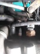
The pipe which Gerald has plugged may well be redundant on yours - there are 2 nipples next to each other on the back of the inlet manifold - 1 has the black elbow attached and goes to the reservoir (and needs to be fitted to allow heater to function)....

.... the 2nd one is usually 'capped' when the car leaves the factory. (I assume that it had a specific function when the engine was used elsewhere, but not needed on an Elan).

This 2nd nipple needs to be capped (or in you case, a pipe fitted and plugged!) so that there is no vacuum leak which will affect the sensors for the engine management.

However

I would suggest that (judging from the length of pipe, and where it ends up) that someone previously has had a dump valve fitted, and used the 'extra' nipple to activate it, instead of fitting a 'tee' piece in another vacuum pipe.
Dave

Just the one now, but this one's mine! - and it will be finished eventually..... - but also temporary custodian of a project until it is finished enough for Angie to drive it


...oh, and a 2006 Freelander destined for the jungles of The Gambia - 4500 miles across roads, desert and tracks - what could possibly go wrong?
User avatar
dapinky
LEC Administrator
 
Posts: 10605
Joined: Sun 15.10.2006, 12:54
Location: As far west as you can get in West Wales before you become Irish (Pembroke Dock).

Re: vacuum pipe identification

Postby scotlan » Mon 11.05.2020, 15:59

dapinky wrote:Mike (and Tony),

The pipe which Gerald has plugged may well be redundant on yours - there are 2 nipples next to each other on the back of the inlet manifold - 1 has the black elbow attached and goes to the reservoir (and needs to be fitted to allow heater to function)....

.... the 2nd one is usually 'capped' when the car leaves the factory. (I assume that it had a specific function when the engine was used elsewhere, but not needed on an Elan).

This 2nd nipple needs to be capped (or in you case, a pipe fitted and plugged!) so that there is no vacuum leak which will affect the sensors for the engine management.

However

I would suggest that (judging from the length of pipe, and where it ends up) that someone previously has had a dump valve fitted, and used the 'extra' nipple to activate it, instead of fitting a 'tee' piece in another vacuum pipe.

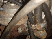
Dave/dapinky Thanks for your input. I feel I have identified one of the two severed vacuum pipe as the one that goes from the elbow on the inlet manifold to the vacuum reservoir. The second one which prompted this post I now believe is the pipe no 2 from diagram 14c also going to the reservoir.
So I am now a bit confused as to what the second outlet pipe from the inlet manifold is for. Does this pipe go the purge line as shown in diagram 02 on this post? This pipe drops down behind the engine and disappears, can be seen in the second pic from the back of the engine.


Image

Image
User avatar
scotlan
Enthusiast
 
Posts: 139
Joined: Sat 01.01.2011, 10:51
Location: Perth, Scotland

Re: vacuum pipe identification - UPDATE

Postby scotlan » Wed 22.07.2020, 08:09

Yesterday, ALL the engine-side vacuum pipes were replaced. I knew there was a vacuum issue as a pipe from the manifold had been severed and I had previously temporarily plugged it with a screw.

However the result was nothing short of AMAZING!

Before: the tickover was a bit high and erratic, there was a bit of a flutter when driving at low reves, performance seemed OK
After: Smooth tickover, no flutter, smooth drive and above all a truly massive boost in acceleration!! I just couldn't believe it. Also the original reason for replacing the pipes, my heater control now operates for the first time since I bought the car.

I bought the pipes, 2metres each of 2 different diameters and some joining connectors for £15. The best £15 I ever spent on a car!
User avatar
scotlan
Enthusiast
 
Posts: 139
Joined: Sat 01.01.2011, 10:51
Location: Perth, Scotland

Re: vacuum pipe identification

Postby Kipperozzy » Wed 22.07.2020, 10:56

Well done Scotlan, for fixing your issues on the cheap and updating the results :D
Kipperozzy
Enthusiast
 
Posts: 199
Joined: Wed 09.03.2016, 15:14
Location: Greenock, Scotland

Next

Return to Turbos, Boost, and Intakes

Who is online

Users browsing this forum: No registered users and 2 guests