
Found something intriguing in the plots. When the O2 Sensor voltage is oscillating nicely, it is possible to compare each 'lean' trough and 'rich' peak with the corresponding fuel injector pulse width (which should have a steady mean value when idling). Using the latest set of data:
So as the sensor voltage falls, heading to 'lean, the Injector pulse width is increased by the ECU to get it back to around 0.5V. As that takes effect and the O2 overshoots that 0.5V point, heading to rich, the injector pulse width is reduced to cause the O2 voltage to decrease, and then repeats. So up to 516 sec all makes sense and looks good. But at 517 sec the O2 voltage is starting to rise but falls abruptly, not clear what causes that step change, but from this point on, the ECU does not increase the injector pulse width to get the O2 voltage back up. So one conclusion is that this really is a 'lean' condition, the O2 sensor is giving valid voltages for that condition and an anomaly is that the ECU did not try to increase the fuel delivery to correct it.
Not clear why the O2 voltage changes abruply, but the Air/Fuel plot shows at this point the slowly ramping ratio snaps to the magic 14.7, so is it that in this warm-up phase the ECU flags that its in closed loop, but infact its in open loop until the coolant temp reaches 35 degC then actually goes closed loop and sets the Air/Fuel ratio to the 14.7 target. Then at that point it is truely closed loop and closed loop just doesn't work, some other input or ECU or ECU connection (maybe CO pot?) is at fault? But I think this does show that the O2 Sensor is working correctly and showing a true lean condition. What do you think?
| Home | WikiLEC | Repairs | Upgrades | Gallery | Buy & Sell | Mountain Chips | Meets & Events | Contact |
|
Lean combustion?
Moderators: theelanman, dapinky, Specky, clemo, Nige, Sy V, Dave Eds, DaveT, Elanlover, muley, Enright, algirdas, nitroman, GeoffSmith
Re: Lean combustion?
 by KenS » Tue 08.09.2026, 14:49
You do not have the required permissions to view the files attached to this post.
S2 M100 NMY #285
N/A 2010 Evora
N/A 2010 Evora
-

KenS - Fanatic
- Posts: 278
- Joined: Mon 27.10.2014, 21:04
- Location: North Kent Coast
Re: Lean combustion?
by Chas54 » Tue 08.09.2026, 15:26
Kens
Ypu may be onto something here , its the first tangible clue anyway.
I have just refitted my old CO adjusting pot to have a test with that in place. I dont think its made any difference though.
Ive done and idling session and then a run on the road and the ECU light comes on still and the engine stutters a bit but its not only on throttle lift offs.
I haven't yet tried replacing the O2 feedback cable although i have tried my meter at the sensor side of the wing plug and can see the voltage drop off on the initial idling period. I think to rule out any induced interference on the cable or poor connection i will cut the cable at the ECU and solder on a new wire that i will (temporarily) run over to the O2 sensor . Probably over the windscreen to be clear . Also i will run a direct +ve from the battery and an earth directly to a terminal block , i can use my higher resistance O2 sensor initially as ive already taken the socket off.
Your suspicion its something else playing a part in this may be true but tracking it down is going to be tricky..
I will have to have a good read of your explanation this evening whilst ive got the elanscan traces in front of me .
Ive attached my CO pot refit elanscans but i cant see anything other than my normal sensor feedback voltage drop offs .
Thanks to everyone for all the great suggestions . Im sure ill get there in the end.
Chas 54
Ypu may be onto something here , its the first tangible clue anyway.
I have just refitted my old CO adjusting pot to have a test with that in place. I dont think its made any difference though.
Ive done and idling session and then a run on the road and the ECU light comes on still and the engine stutters a bit but its not only on throttle lift offs.
I haven't yet tried replacing the O2 feedback cable although i have tried my meter at the sensor side of the wing plug and can see the voltage drop off on the initial idling period. I think to rule out any induced interference on the cable or poor connection i will cut the cable at the ECU and solder on a new wire that i will (temporarily) run over to the O2 sensor . Probably over the windscreen to be clear . Also i will run a direct +ve from the battery and an earth directly to a terminal block , i can use my higher resistance O2 sensor initially as ive already taken the socket off.
Your suspicion its something else playing a part in this may be true but tracking it down is going to be tricky..
I will have to have a good read of your explanation this evening whilst ive got the elanscan traces in front of me .
Ive attached my CO pot refit elanscans but i cant see anything other than my normal sensor feedback voltage drop offs .
Thanks to everyone for all the great suggestions . Im sure ill get there in the end.
Chas 54
You do not have the required permissions to view the files attached to this post.
- Chas54
- Enthusiast
- Posts: 243
- Joined: Mon 13.05.2019, 11:36
- Location: Market Rasen, Lincolnshire
Re: Lean combustion?
by KenS » Tue 08.09.2026, 17:57
With the CO pot it does look the same. Where the O2 sensor drops out during warm-up (143 sec ) has the same characteristics, it happens when the coolant is at 35 degC, and the Air/Fuel ratio suddenly jumps to 14.7 (real closed loop point).
I've checked a few other reference plots and so far they show the same point of interest, when the coolant reaches 35degC the Air/Fuel ratio jumps to 14.7 and a disturbance in the O2 sensor voltage, but in those cases the Injector pulse widths continue to recover the small upset in the O2 voltage. An example of a good archived reference plot where O2 Sensor continues through that 35degC point (76 seconds):
So I wonder what additional parameters are involved in setting the injector pulse width when the coolant is above 35degC????
I've checked a few other reference plots and so far they show the same point of interest, when the coolant reaches 35degC the Air/Fuel ratio jumps to 14.7 and a disturbance in the O2 sensor voltage, but in those cases the Injector pulse widths continue to recover the small upset in the O2 voltage. An example of a good archived reference plot where O2 Sensor continues through that 35degC point (76 seconds):
So I wonder what additional parameters are involved in setting the injector pulse width when the coolant is above 35degC????
You do not have the required permissions to view the files attached to this post.
S2 M100 NMY #285
N/A 2010 Evora
N/A 2010 Evora
-
KenS - Fanatic
- Posts: 278
- Joined: Mon 27.10.2014, 21:04
- Location: North Kent Coast
Re: Lean combustion?
by chrism » Tue 08.09.2026, 18:54
Yep looked at all the other traces and 35C features as the beginnings of O2 decline in all of them. Surely not a coincidence?
Fan sensor's okay, new CTS and display temp seems okay. I can't see anything in my own m100 data that changes at 35C...
So, why 35C, I wonder??? And with the same 1499 memcal in two different ecus. Try a different memcal then? Could the new 1499 memcal be at fault? (Again, I've got a spare...)
Fan sensor's okay, new CTS and display temp seems okay. I can't see anything in my own m100 data that changes at 35C...
So, why 35C, I wonder??? And with the same 1499 memcal in two different ecus. Try a different memcal then? Could the new 1499 memcal be at fault? (Again, I've got a spare...)
-
chrism - God
- Posts: 894
- Joined: Sun 16.01.2022, 14:36
- Location: West Sussex, UK
Re: Lean combustion?
by Chas54 » Tue 08.09.2026, 19:38
KenS
Ive been looking at the points you picked up and agree something must happen but cant see anything from the other points .
I thought i would have a look at the exact point the O2 sensor voltage starts appearing again but cant see any correlating facts,,
I have been looking at the flags but i only really know flag 42 is the closed cycle , on or off .
Ive some effective leads made up and just have the ECU pin D7 to splice in to tomorrow then i can run the engine and drive with the O2 sensor cables assured.
Chas 54
Ive been looking at the points you picked up and agree something must happen but cant see anything from the other points .
I thought i would have a look at the exact point the O2 sensor voltage starts appearing again but cant see any correlating facts,,
I have been looking at the flags but i only really know flag 42 is the closed cycle , on or off .
Ive some effective leads made up and just have the ECU pin D7 to splice in to tomorrow then i can run the engine and drive with the O2 sensor cables assured.
Chas 54
- Chas54
- Enthusiast
- Posts: 243
- Joined: Mon 13.05.2019, 11:36
- Location: Market Rasen, Lincolnshire
Re: Lean combustion?
by KenS » Tue 08.09.2026, 20:16
It looks like the ECU starts involving more inputs once it warmed up to 35degC, so I have been looking for any data that is different between your type plots and gold std references in the period leading up to 35DegC. So far found 3 things that are different.
1/ Crank Alt Fire (failing plot - upper, good reference plot lower, both roughly centered on that 35degC point):
2/ Cyl Num 2
3/ Cyl Num 4 (haven't printed it but looks very similar to Cyl Num 2)
No idea what these are or if they could be relavent. Not sure if the Cyl Num 2 and 4 plots have been distorted by the ElanScan interface sampling/resolution, the plots may not be showing the true exact waveforms. But likely that Crank Alt Fire will be related to those signals so seems that they probably do differ between your plots and the reference.
How do we find out what these are and if they are relavent to the problem? Chrism - Does Pete know the inner secrets of the Engine Management System?
1/ Crank Alt Fire (failing plot - upper, good reference plot lower, both roughly centered on that 35degC point):
2/ Cyl Num 2
3/ Cyl Num 4 (haven't printed it but looks very similar to Cyl Num 2)
No idea what these are or if they could be relavent. Not sure if the Cyl Num 2 and 4 plots have been distorted by the ElanScan interface sampling/resolution, the plots may not be showing the true exact waveforms. But likely that Crank Alt Fire will be related to those signals so seems that they probably do differ between your plots and the reference.
How do we find out what these are and if they are relavent to the problem? Chrism - Does Pete know the inner secrets of the Engine Management System?
You do not have the required permissions to view the files attached to this post.
S2 M100 NMY #285
N/A 2010 Evora
N/A 2010 Evora
-
KenS - Fanatic
- Posts: 278
- Joined: Mon 27.10.2014, 21:04
- Location: North Kent Coast
Re: Lean combustion?
by chrism » Tue 08.09.2026, 22:54
I'll phone Peter tomorrow and get back asap...
Meanwhile let's look forward to the lead substitution.
Meanwhile let's look forward to the lead substitution.
-
chrism - God
- Posts: 894
- Joined: Sun 16.01.2022, 14:36
- Location: West Sussex, UK
Re: Lean combustion?
by Chas54 » Wed 09.09.2026, 09:36
Chrism
Thats very interesting . and if its 2 and 4 suspect they are on different coil packs. The "Crank Alt Firing" is something i don't know, but it sounds a lot like the the management of spark timing within the ECU and using the CAS as its crank reference point. It would fit with me seeing at sometimes the spark advanced to greater values than i would believe sensible .. But i am more used to tuning carb engines and ignition advances of 20 degrees maximum .
The reluctor wheel and its inductive capacity must now come under suspicion.. As my problem seems now to occur when the car is being driven, i think it wont be easy to track this down.
I changed the CAS a couple of years ago and wondered then about play in the drive bearings but the amount seems very small .
Anyway , Im still planning today to cut the ECU pin D7 cable and replace it along with my jumper cables to the O2 sensor for a definitive test . Ive got to come up with a quick way to disconnect the O2 sensor live from the battery. Just in case the engine stops , i don't want to leave the O2 sensor heating without the gas flow across it. I could use a jump lead from the battery +ve to the passenger seat and a crocodile clip there to a cable to the sensor , be handy to clip on once engine started and unclip if engine stops .
It would be good to hear any suggestions from an ECU guru as to what the ECU does .. And the "crank alt firing" factor.
Thanks again to all for comments , i am outside my comfort zone with this sophisticated system.
Chas%$
Thats very interesting . and if its 2 and 4 suspect they are on different coil packs. The "Crank Alt Firing" is something i don't know, but it sounds a lot like the the management of spark timing within the ECU and using the CAS as its crank reference point. It would fit with me seeing at sometimes the spark advanced to greater values than i would believe sensible .. But i am more used to tuning carb engines and ignition advances of 20 degrees maximum .
The reluctor wheel and its inductive capacity must now come under suspicion.. As my problem seems now to occur when the car is being driven, i think it wont be easy to track this down.
I changed the CAS a couple of years ago and wondered then about play in the drive bearings but the amount seems very small .
Anyway , Im still planning today to cut the ECU pin D7 cable and replace it along with my jumper cables to the O2 sensor for a definitive test . Ive got to come up with a quick way to disconnect the O2 sensor live from the battery. Just in case the engine stops , i don't want to leave the O2 sensor heating without the gas flow across it. I could use a jump lead from the battery +ve to the passenger seat and a crocodile clip there to a cable to the sensor , be handy to clip on once engine started and unclip if engine stops .
It would be good to hear any suggestions from an ECU guru as to what the ECU does .. And the "crank alt firing" factor.
Thanks again to all for comments , i am outside my comfort zone with this sophisticated system.
Chas%$
- Chas54
- Enthusiast
- Posts: 243
- Joined: Mon 13.05.2019, 11:36
- Location: Market Rasen, Lincolnshire
Re: Lean combustion?
by KenS » Wed 09.09.2026, 09:55
Google AI does seem to know a bit about the Elan Engine Management:
I'll have a look across more plots to see how significant the difference in 0 and 2 is for this 'Crank Alt Fire', so far I have assumed its 0 = off 2= on, but may be wrong.
I'll have a look across more plots to see how significant the difference in 0 and 2 is for this 'Crank Alt Fire', so far I have assumed its 0 = off 2= on, but may be wrong.
You do not have the required permissions to view the files attached to this post.
S2 M100 NMY #285
N/A 2010 Evora
N/A 2010 Evora
-
KenS - Fanatic
- Posts: 278
- Joined: Mon 27.10.2014, 21:04
- Location: North Kent Coast
Re: Lean combustion?
by KenS » Wed 09.09.2026, 10:08
And asking AI for when Crank Alt Fire it is set active:
You do not have the required permissions to view the files attached to this post.
S2 M100 NMY #285
N/A 2010 Evora
N/A 2010 Evora
-
KenS - Fanatic
- Posts: 278
- Joined: Mon 27.10.2014, 21:04
- Location: North Kent Coast
Re: Lean combustion?
by Chas54 » Wed 09.09.2026, 10:42
WOW , ive previously written off AI as Artificial Interference and never found it any use and a real annoyance.
you may have swayed me in favour now though ..
The CAS then is an area i will revisit this morning while its cool enough to play with..
I'll check the easy stuff like the gaps and the play first.
Thanks KenS
Chas54
you may have swayed me in favour now though ..
The CAS then is an area i will revisit this morning while its cool enough to play with..
I'll check the easy stuff like the gaps and the play first.
Thanks KenS
Chas54
- Chas54
- Enthusiast
- Posts: 243
- Joined: Mon 13.05.2019, 11:36
- Location: Market Rasen, Lincolnshire
Re: Lean combustion?
by Tuga2112 » Wed 09.09.2026, 11:48
i think one needs to be cautious of artificial idiocy, its nice to see its summary about something. but often when asked to site its resources you find them to be of little or no authority
Still learning
Youtube Channel @Tuga2112 M100 repair videos
Youtube Channel @Tuga2112 M100 repair videos
-

Tuga2112 - God
- Posts: 3039
- Joined: Fri 12.09.2014, 22:54
- Location: Durham with a regular trip to Walsall
Re: Lean combustion?
by KenS » Wed 09.09.2026, 11:50
So it looks like the ECU still thinks its in cranking or low engine speed (below 800rpm) ? Looked at section EMK2 Q-T but cannot work out who flags when the speed is greater than 800 rpm, is it the Ignition base plate via the magnetic pick-up or the hall effect sensor or is it the ECU itself? There is a Bypass control connection between the ECU and Coil base plate, could that be it?
You do not have the required permissions to view the files attached to this post.
S2 M100 NMY #285
N/A 2010 Evora
N/A 2010 Evora
-
KenS - Fanatic
- Posts: 278
- Joined: Mon 27.10.2014, 21:04
- Location: North Kent Coast
Re: Lean combustion?
by Chas54 » Wed 09.09.2026, 12:19
KenS
I think the hall effect device is for the injector timing and the magnetic sensor for the ignition . Im guessing the 800 rpm when the ignition pack hands over to the ECU is decided within the ECU.
Ive just taken of the CAS and the only play is at the drive end but it is between the two halves of the coupling exhaust can drive to CAS drive . On the bench there is no play.
Ive closed the magnetic sensor gap from 9 thou to 5 thou just to see if i can detect any difference . I cant see where you found the flag for the Alt Crank firing.
anyway here's a quick warm up scan which includes the same strange O2 sensor feedback voltage drop.
I have to take the car out on the road to check if it still drops off while im driving. I think ill do irt before I bite the bullet and chop through my ECU cable .
Chas54
I think the hall effect device is for the injector timing and the magnetic sensor for the ignition . Im guessing the 800 rpm when the ignition pack hands over to the ECU is decided within the ECU.
Ive just taken of the CAS and the only play is at the drive end but it is between the two halves of the coupling exhaust can drive to CAS drive . On the bench there is no play.
Ive closed the magnetic sensor gap from 9 thou to 5 thou just to see if i can detect any difference . I cant see where you found the flag for the Alt Crank firing.
anyway here's a quick warm up scan which includes the same strange O2 sensor feedback voltage drop.
I have to take the car out on the road to check if it still drops off while im driving. I think ill do irt before I bite the bullet and chop through my ECU cable .
Chas54
You do not have the required permissions to view the files attached to this post.
- Chas54
- Enthusiast
- Posts: 243
- Joined: Mon 13.05.2019, 11:36
- Location: Market Rasen, Lincolnshire
Re: Lean combustion?
by chrism » Wed 09.09.2026, 13:19
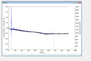
Don't wanna criticise folks but my Crank Alt Fire (black) follows Chas' blue trace and 'stays active'. Might just be a CAS blind alley?
-
chrism - God
- Posts: 894
- Joined: Sun 16.01.2022, 14:36
- Location: West Sussex, UK
Re: Lean combustion?
by KenS » Wed 09.09.2026, 14:36
Chrism - I have check back across several old plots and this is a bit odd now. My plots going back a couple of years show CrankAltFire at 0, so maybe mine are in error. I have a few random plots from other people but cannot be sure whos or under what conditions, some show 0 (eg Home2Costco, ROJ, DJH1), and one at 2 (DJH2). Its clear that some of those runs are not running well. Need to go back through the Forum and try to find known good plots to see what the pattern is.
Chas54, the Crank Alt Fire is well down the selection list, I think it only shows if you use the latest version of ElanScan and its updated ini file viewtopic.php?f=34&t=30234
Chas54, the Crank Alt Fire is well down the selection list, I think it only shows if you use the latest version of ElanScan and its updated ini file viewtopic.php?f=34&t=30234
You do not have the required permissions to view the files attached to this post.
S2 M100 NMY #285
N/A 2010 Evora
N/A 2010 Evora
-
KenS - Fanatic
- Posts: 278
- Joined: Mon 27.10.2014, 21:04
- Location: North Kent Coast
Re: Lean combustion?
by Tuga2112 » Wed 09.09.2026, 15:09
KenS wrote:So it looks like the ECU still thinks its in cranking or low engine speed (below 800rpm) ? Looked at section EMK2 Q-T but cannot work out who flags when the speed is greater than 800 rpm,[/attachment]
the engine RPM signal goes into the instrument cluster directly from the spark control module (the place that holds the coil packs
i would be checking if the signal is then forwarded to the ECU from there. if theres other issues with the instrument cluster this could be a variation on the same theme that Trevor had last year with hes speed sensor signal not making its way to the ECU
Still learning
Youtube Channel @Tuga2112 M100 repair videos
Youtube Channel @Tuga2112 M100 repair videos
-
Tuga2112 - God
- Posts: 3039
- Joined: Fri 12.09.2014, 22:54
- Location: Durham with a regular trip to Walsall
Re: Lean combustion?
by Chas54 » Wed 09.09.2026, 16:58
I havent managed to insert a new cable from the ECU to the O2 sensor yet.
I disconnected the battery and unplugged the ECU J2 plug and took the locking clips off each side . I havent really got enough cable to splice anything in, and then if no improvement reconnect. I had hoped to find enough slack to be able to access with a soldering iron but the cables are really short . But having heaved and stretched the cable i thought id better ring it through from the O2 plug . Its a good connection so if there is anything wrong it must be some electrical induction somewhere.
During the process of pulling at them to get enough slack i did pull the next pin downs cable . Thats the D8 pin and found some slack wire here but it is looped back into the plug around to the D13 pin . Both of these are "peak and hold" circuit which sounds like injectors to me . My question is ... is this right ??
Tuga's suggestion in worth looking at but im not sure where the engine speed is fed back from the tacho to the ECU ,
I ran the car after my frustration wore off just to make sure i hadnt damaged any connections , It ran OK but had to feather the throttle to keep it going , learned memory wiped with the battery loss. This was a warm run up to idle and i noticed that it took some time to start the O2 sensor considering all the heat was already in the engine. The profile looks similar but at a lot higher temperature. A bit strange I think.
Chas54
I disconnected the battery and unplugged the ECU J2 plug and took the locking clips off each side . I havent really got enough cable to splice anything in, and then if no improvement reconnect. I had hoped to find enough slack to be able to access with a soldering iron but the cables are really short . But having heaved and stretched the cable i thought id better ring it through from the O2 plug . Its a good connection so if there is anything wrong it must be some electrical induction somewhere.
During the process of pulling at them to get enough slack i did pull the next pin downs cable . Thats the D8 pin and found some slack wire here but it is looped back into the plug around to the D13 pin . Both of these are "peak and hold" circuit which sounds like injectors to me . My question is ... is this right ??
Tuga's suggestion in worth looking at but im not sure where the engine speed is fed back from the tacho to the ECU ,
I ran the car after my frustration wore off just to make sure i hadnt damaged any connections , It ran OK but had to feather the throttle to keep it going , learned memory wiped with the battery loss. This was a warm run up to idle and i noticed that it took some time to start the O2 sensor considering all the heat was already in the engine. The profile looks similar but at a lot higher temperature. A bit strange I think.
Chas54
You do not have the required permissions to view the files attached to this post.
- Chas54
- Enthusiast
- Posts: 243
- Joined: Mon 13.05.2019, 11:36
- Location: Market Rasen, Lincolnshire
Re: Lean combustion?
by chrism » Wed 09.09.2026, 17:03
KenS, agreed. I'm gonna trawl all my old EScans. Unfortunately many of mine are from pals who had problems...
The one I used on my comparison was from my m100 on 10/04/26. Everything's running fine and CrankAltFire starts on 1.
Of course I'll trawl thro' my scans but wouldn't it be easier to ask fellow LEC-ers to check their own and report back whether CrankAltFire starts from 0, 1 or 2? It seems that 0 means poor running from your traces so we're looking for 2's OR 1's. for healthy-running m100s? Chas54's is momentarily on 2 then drops quickly to 1...
Edit - sorry folks I found two of my 'good' plots running from 2. It's hard work knowing which plots to use so I'm off out to run an EScan in 5mins so's I know it's a good scan...and I can report back accurately
The one I used on my comparison was from my m100 on 10/04/26. Everything's running fine and CrankAltFire starts on 1.
Of course I'll trawl thro' my scans but wouldn't it be easier to ask fellow LEC-ers to check their own and report back whether CrankAltFire starts from 0, 1 or 2? It seems that 0 means poor running from your traces so we're looking for 2's OR 1's. for healthy-running m100s? Chas54's is momentarily on 2 then drops quickly to 1...
Edit - sorry folks I found two of my 'good' plots running from 2. It's hard work knowing which plots to use so I'm off out to run an EScan in 5mins so's I know it's a good scan...and I can report back accurately
-
chrism - God
- Posts: 894
- Joined: Sun 16.01.2022, 14:36
- Location: West Sussex, UK
Return to Ignition and fuelling
Who is online
Users browsing this forum: KenS and 0 guests